Getting Started
What You'll Need
Before starting with your Kaush Sound Sensor v1.0, ensure you have all the required components and software ready.
Hardware Requirements
Essential Components:
- ✅Kaush Sound Sensor v1.0
- ✅Microcontroller (Arduino Nano, ESP32, or Raspberry Pi)
- ✅USB cable (for programming the microcontroller)
- ✅Jumper wires (male-to-female recommended)
- ✅Breadboard (optional, but highly recommended for prototyping)
- ✅Power supply (4V–12V) or USB power
Optional Components:
- 🔧Multimeter → For verifying voltage and connections
- 🔧Audio source (speaker, phone, or buzzer) → For testing sound detection
Software Requirements
For Microcontroller Programming:
- Arduino IDE (v1.8.0 or later)
- USB drivers for your microcontroller
- Kaush Sound Sensor library (provided)
Step-by-Step Setup
Step 1: Choose Your Platform
Select your preferred microcontroller platform. Each has its advantages:
Option A: Arduino Nano (Recommended for Beginners)
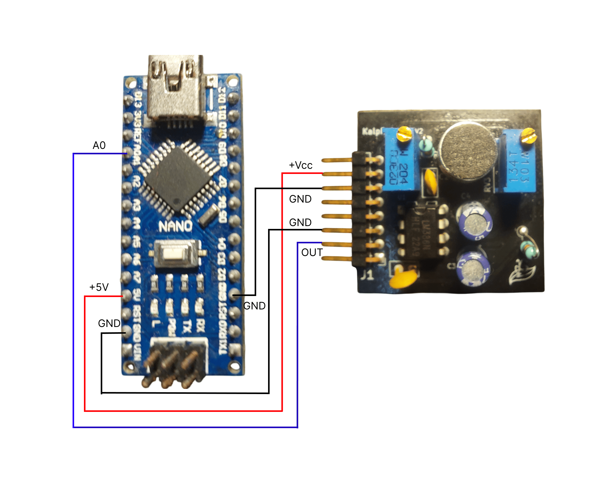 Complete Arduino Nano setup with Kaush Sound Sensor
Advantages: - Easy to program with Arduino IDE - 5V operation matches sensor well - Large community support - Real-time sampling up to 4kHz
Option B: ESP32 (WiFi Enabled)
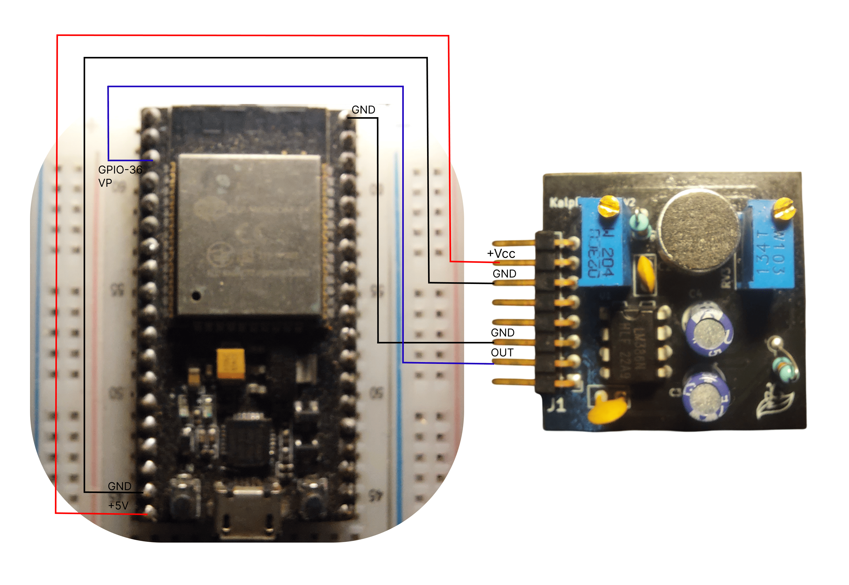 ESP32 setup enabling wireless data transmission
Advantages: - Built-in WiFi for wireless data - Higher processing power - IoT integration capabilities - Web-based control possible
Option C: Raspberry Pi (Advanced Features)
Advantages:
- Linux-based advanced processing
- Multiple communication interfaces
- Can run desktop application directly
- Real-time DSP capabilities
Step 3: Basic Wiring (Arduino Nano Example)
Connection Table:
| Kaush Sensor Pin | Arduino Nano Pin | Function |
|---|---|---|
| VCC | 5V | Power Supply |
| GND | GND | Ground |
| FILTERED_OUT | A0 | Analog Signal |
Step 4: Power Supply Connection
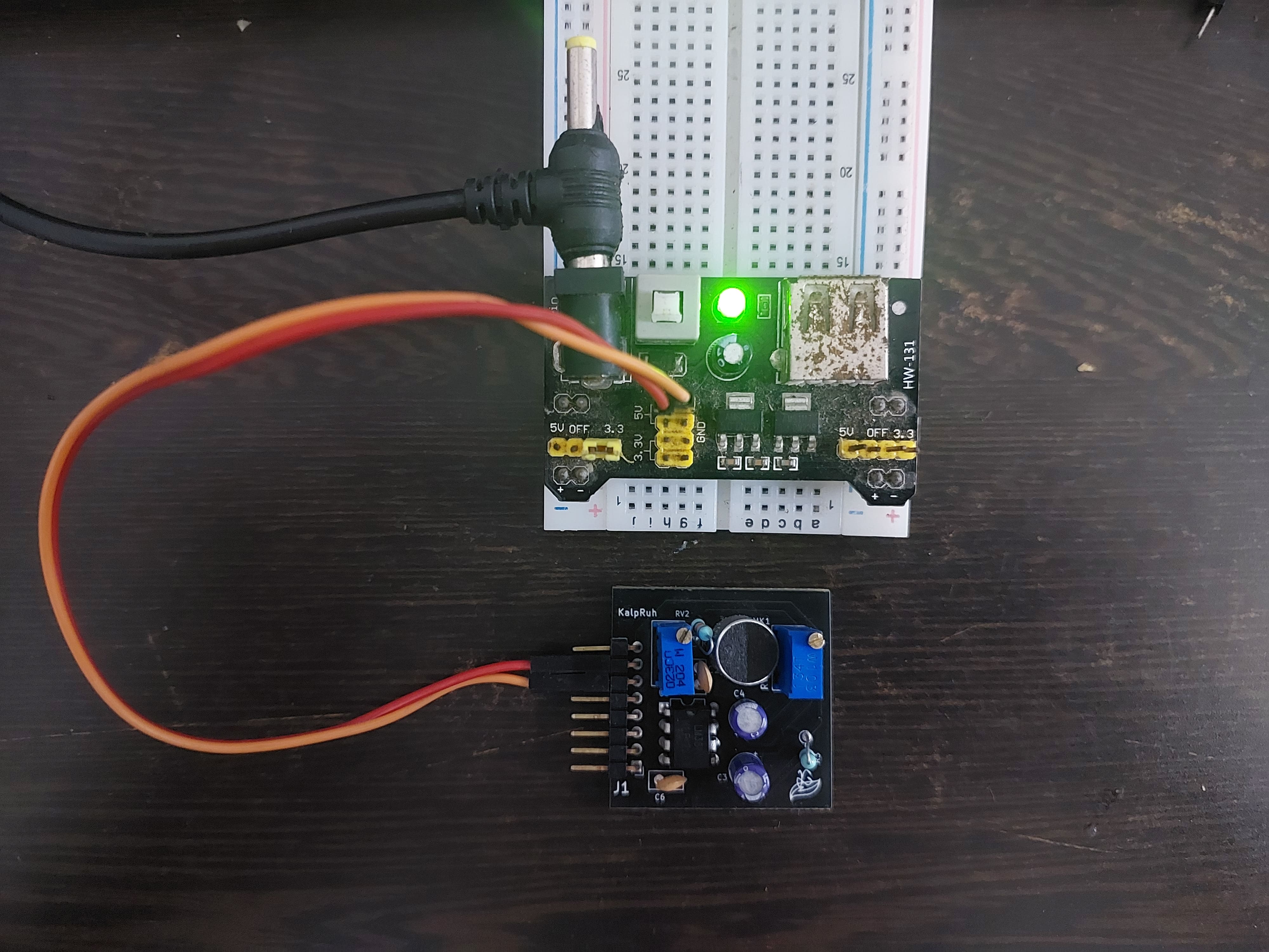 Different power supply methods for the sensor
Power Options:
USB Power (5V) - Simplest Method
Arduino Nano USB → Computer USB Port
Sensor VCC → Arduino 5V Pin
Sensor GND → Arduino GND Pin
External Power (6V-12V) - Maximum Performance
External Supply → Arduino VIN Pin
Sensor VCC → Arduino 5V Pin (regulated)
Sensor GND → Arduino GND Pin
Battery Power (Portable Operation)
4x AA Batteries (6V) → Arduino VIN Pin
Or 9V Battery → Arduino VIN Pin
Step 5: Software Installation
Download Required Software
Arduino IDE Setup:
- Download Arduino IDE from arduino.cc
- Install USB drivers for your microcontroller
- Download Kaush Sound Sensor library from our GitHub
Library Installation
Method 1: Arduino IDE Library Manager
- Open Arduino IDE
- Go to
Sketch → Include Library → Manage Libraries - Search for "Kaush Sound Sensor"
- Click Install
Method 2: Manual Installation
- Download library ZIP from GitHub
- Go to
Sketch → Include Library → Add .ZIP Library - Select downloaded ZIP file
- Verify installation in
Examples → Kaush Sound Sensor
Step 6: Upload Test Code
Basic Test Code:
- Open Arduino IDE
- Go to
File → Examples → Kaush Sound Sensor → BasicTest - Select correct board:
Tools → Board → Arduino Nano - Select correct port:
Tools → Port → COM_X - Click Upload button
Step 7: Initial Calibration
Calibration Procedure:
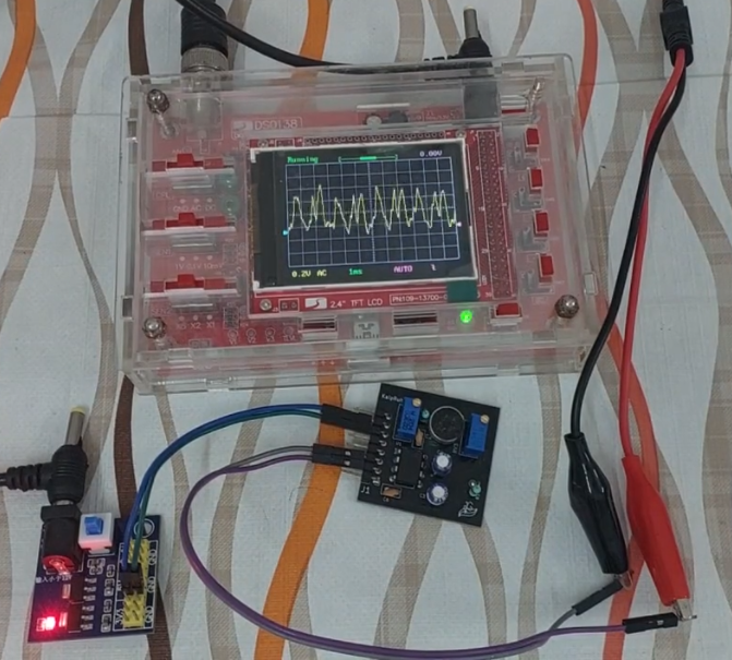
8.1 Baseline Setting
- Environment: Start in quiet environment
- 200K Pot: Turn clockwise until you see waveform on the Kaush Software (12 o'clock)
- 10K Pot: Once 200k pot is successfully calibrated, you can turn this clock-wise to increase the gain and anticlock-wise to decrease the gain
- Monitor: Watch serial output for baseline ~VCC/2
8.2 Sensitivity Adjustment
- Test Sound: Speak normally at 30cm distance
- 200K Pot: Slowly increase until clear signal appears
- Fine-tuning: Adjust 10K Pot for desired amplitude (1-2V peak)
- Verification: Test at different distances
8.3 Optimal Settings
Quiet Environment:

- Expected Output: 1.5V baseline, 2-3V with speech

Noisy Environment:

- Expected Output: Reduced baseline, clear speech signals
Quick Start Video Tutorial
Complete Setup Guide
Watch our comprehensive setup tutorial covering all steps:
Potential First-Time Issues
Issue 1: No Serial Output
Symptoms: Arduino IDE serial monitor shows no data Solutions:
- Verify COM port selection
- Check baud rate (115200)
- Ensure USB cable supports data (not charge-only)
- Try different USB port
- Calibrate Sensor Again
- Reconnect supply or try different Power Supply
- Push the reset/restart button of microcontroller(ESP32 or Arduino)
Issue 2: Constant High/Low Readings
Symptoms: Sensor output stuck at 0V or VCC Solutions:
- Check power supply voltage (4-12V range)
- Verify wiring connections
- Adjust 200K potentiometer
- Test with multimeter
- Check whether GND and VCC are swapped accidentally
Issue 3: No Response to Sound
Symptoms: Output doesn't change with audio input Solutions:
- Increase 10K potentiometer (gain)
- Verify microphone is not blocked
- Test with louder sounds first
- Check pre-amp output (A2 pin)
- Clean the bottom side of sensor
Issue 4: Desktop App Won't Connect
Symptoms: Cannot establish COM port connection Solutions:
- Install Arduino USB drivers
- Close Arduino IDE serial monitor
- Check Windows Device Manager
- Check Arduino
Success Indicators
When your setup is working correctly, you should see:
- 🟢 Stable baseline around VCC/2 in quiet conditions
- 🟢 Clear waveforms when speaking at normal volume
- 🟢 Responsive adjustments when turning potentiometers
- 🟢 Real-time display in desktop application
- 🟢 Meaningful FFT data showing voice frequencies
Next Steps
Congratulations on completing the basic setup! You're now ready to:
- Explore Pin Configuration - Learn about advanced wiring options
Need Help?
- 📺 Video Tutorials: Edge Neuron YouTube Channel
- 💻 Code Repository: GitHub - Edge-Neuron
- 🔧 Troubleshooting: Common Issues Guide
Ready to dive deeper? Continue to Pin Configuration for advanced connection options.