Pin Configuration & Wiring
Pin Layout Overview
The Kaush Sound Sensor v1.0 features a compact 8-pin interface that provides maximum flexibility for different applications and microcontroller platforms.
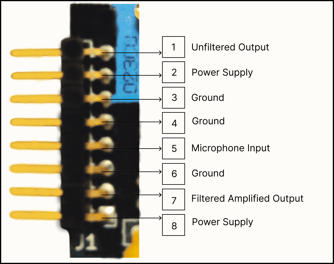
Detailed pin layout with electrical specifications
Pin Definitions
Power Pins
VCC (Positive Power Supply)
- Voltage Range: 4V to 12V DC
- Current Draw: 4mA quiescent, 15mA peak
- Recommended: 5V (Arduino) or 9V (battery)
- Protection: ⚠️ Not Reverse Polarity Protected
- Connection: Two power connection pins provided
GND (Ground Reference)
- Function: 0V reference and return path
- Connection: Must connect to microcontroller ground
- Important: Single ground point recommended
Signal Output Pins
FILTERED_OUT (RC Filtered Output)
- Signal Type: Analog, AC-coupled
- Baseline: VCC/2 (Half supply voltage)
- Amplitude: 0.5V to 3V peak-to-peak
- Bandwidth: ~20Hz to 10kHz (-3dB)
- Impedance: <1kΩ output impedance
- Best For: General audio processing, speech recognition
RAW_OUT (Unfiltered Output)
- Signal Type: Analog, full bandwidth
- Baseline: VCC/2
- Amplitude: 0.5V to 3V peak-to-peak
- Bandwidth: DC to 20kHz
- Impedance: <500Ω output impedance
- Best For: Maximum signal fidelity, custom filtering
PRE_AMP (Pre-Amplification Signal)
- Signal Type: Analog, low amplitude
- Baseline: VCC/2
- Amplitude: 10mV to 200mV peak-to-peak
- Gain: No LM386 amplification applied
- Best For: Low-noise applications, external amplification
Platform-Specific Wiring
Arduino Nano Configuration
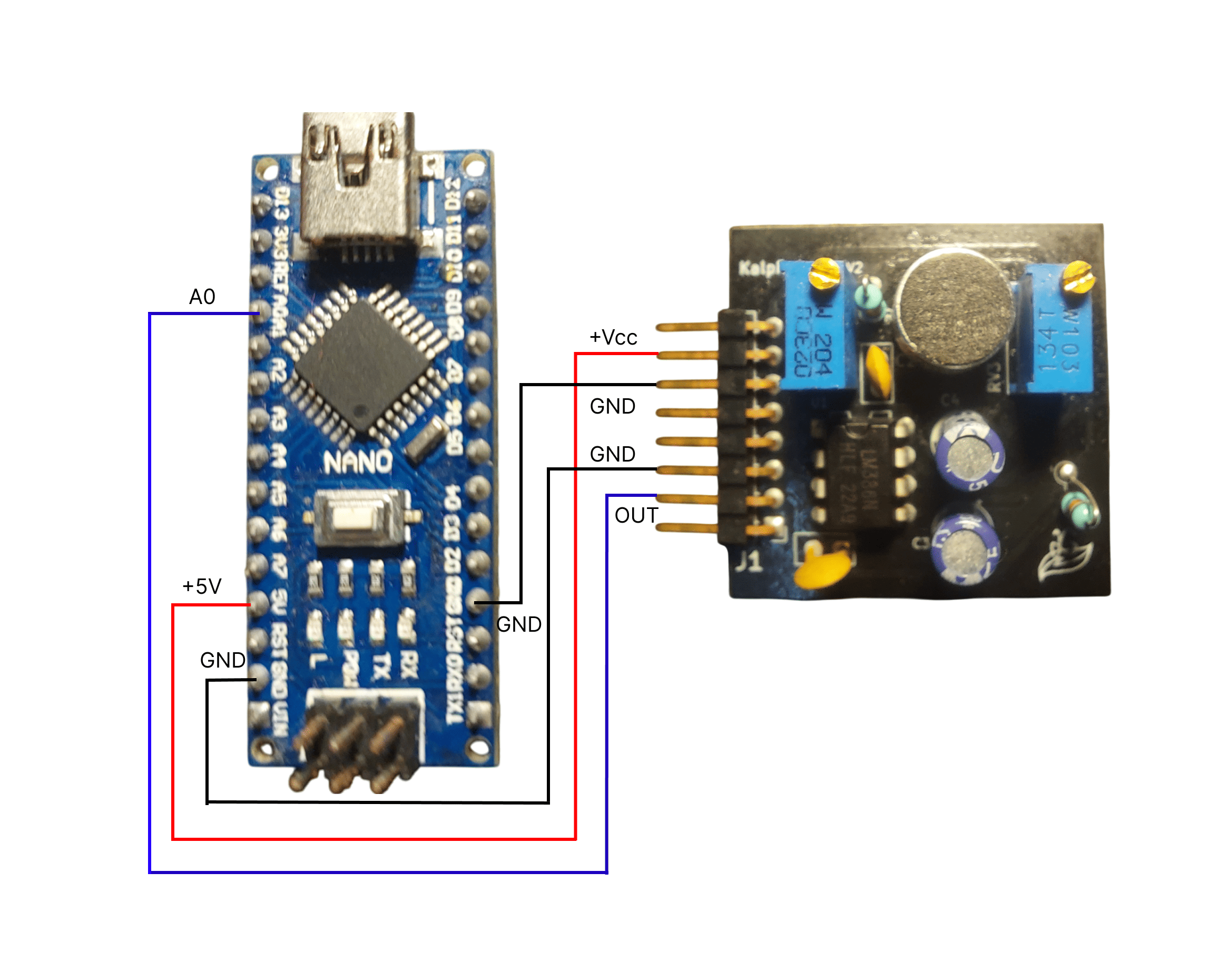 Complete Arduino Nano connection diagram
Standard Connection
Kaush Sensor    →    Arduino Nano
VCC             →    5V
GND             →    GND
FILTERED_OUT    →    A0
RAW_OUT         →    A1 (optional)
PRE_AMP         →    A2 (optional)
Code Example
// Pin definitions
#define FILTERED_PIN A0
#define RAW_PIN A1
#define PREAMP_PIN A2

void setup() {
  Serial.begin(115200);
  // Analog pins are input by default
}

void loop() {
  int filtered = analogRead(FILTERED_PIN);
  int raw = analogRead(RAW_PIN);
  int preamp = analogRead(PREAMP_PIN);

  Serial.print("Filtered: "); Serial.print(filtered);
  Serial.print(" Raw: "); Serial.print(raw);
  Serial.print(" PreAmp: "); Serial.println(preamp);

  delay(1); // 1ms = 1kHz sampling
}
ESP32 Configuration
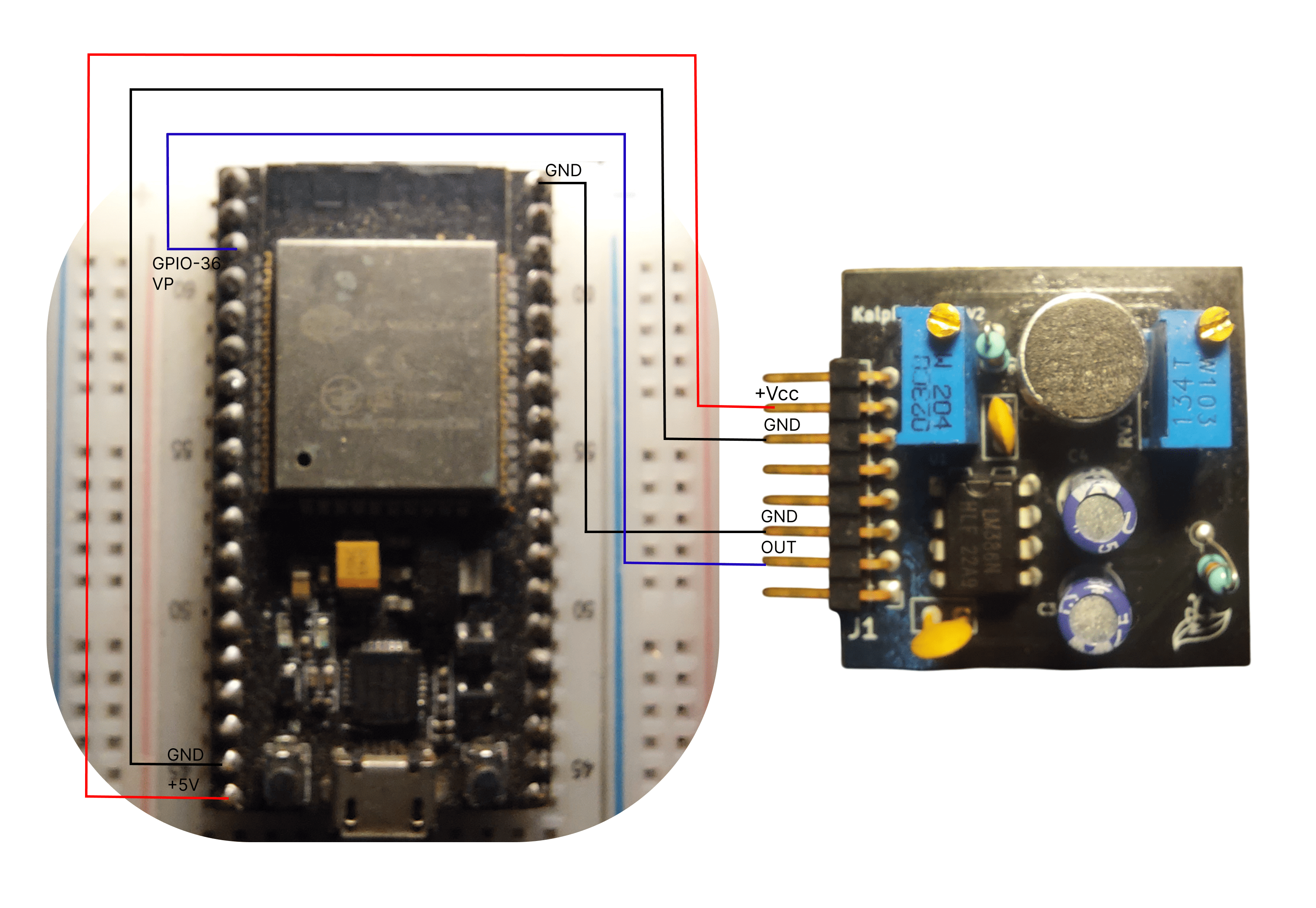 ESP32 wiring with voltage considerations
ESP32 Connection
Kaush Sensor    →    ESP32
VCC             →    5V
GND             →    GND
FILTERED_OUT    →    36
ESP8266 Connection
Kaush Sensor    →    ESP8266
VCC             →    3V3(3.3V)
GND             →    GND
FILTERED_OUT    →    A0
Voltage Warning
ESP8266 analog input is 0-1V only! Use voltage divider for 3.3V sensor output:
WiFi-Enabled Code Example
#include <ESP8266WiFi.h>

#define SENSOR_PIN A0
const char* ssid = "your_wifi_name";
const char* password = "your_password";

WiFiServer server(80);

void setup() {
  Serial.begin(115200);
  WiFi.begin(ssid, password);
  server.begin();
}

void loop() {
  int sensorValue = analogRead(SENSOR_PIN);
  // Scale from 1024 to compensate for voltage divider
  float actualVoltage = (sensorValue / 1024.0) * 3.3 * 1.67;

  WiFiClient client = server.available();
  if (client) {
    client.print("HTTP/1.1 200 OK\r\nContent-Type: text/plain\r\n\r\n");
    client.print("Sound Level: ");
    client.println(actualVoltage);
    client.stop();
  }

  delay(10);
}
Raspberry Pi Configuration
Using MCP3008 ADC (Recommended)
Kaush Sensor    →    MCP3008 ADC    →    Raspberry Pi
VCC             →    VDD (3.3V)     →    3.3V (Pin 1)
GND             →    VSS/AGND       →    GND (Pin 6)
FILTERED_OUT    →    CH0            →
                     SCLK           →    GPIO 11 (Pin 23)
                     MOSI           →    GPIO 10 (Pin 19)
                     MISO           →    GPIO 9 (Pin 21)
                     CS             →    GPIO 8 (Pin 24)
Python Code Example
import spidev
import time

# Setup SPI for MCP3008
spi = spidev.SpiDev()
spi.open(0, 0)  # Bus 0, Device 0
spi.max_speed_hz = 1350000

def read_adc(channel):
    # MCP3008 protocol
    r = spi.xfer2([1, (8 + channel) << 4, 0])
    adc_out = ((r[1] & 3) << 8) + r[2]
    return adc_out

try:
    while True:
        sensor_value = read_adc(0)  # Channel 0
        voltage = (sensor_value / 1023.0) * 3.3
        print(f"Sensor: {sensor_value:4d} Voltage: {voltage:.2f}V")
        time.sleep(0.1)

except KeyboardInterrupt:
    spi.close()
Advanced Wiring Configurations
Multi-Sensor Setup
Stereo Configuration (2 Sensors)
Sensor 1 (Left):
VCC → 5V (shared)
GND → GND (shared)
FILTERED_OUT → A0

Sensor 2 (Right):
VCC → 5V (shared)
GND → GND (shared)
FILTERED_OUT → A1
4-Sensor Array
#define SENSOR_N A0  // North
#define SENSOR_S A1  // South
#define SENSOR_E A2  // East
#define SENSOR_W A3  // West

void loop() {
  int north = analogRead(SENSOR_N);
  int south = analogRead(SENSOR_S);
  int east = analogRead(SENSOR_E);
  int west = analogRead(SENSOR_W);

  // Calculate sound direction
  float vertical = (north - south) / (float)(north + south);
  float horizontal = (east - west) / (float)(east + west);

  Serial.print("Direction - V: "); Serial.print(vertical);
  Serial.print(" H: "); Serial.println(horizontal);

  delay(10);
}
Signal Analysis Connections
Spectrum Analyzer Setup
Real-Time FFT Monitoring
#include "arduinoFFT.h"

#define SAMPLES 256
#define SAMPLING_FREQUENCY 2000

double vReal[SAMPLES];
double vImag[SAMPLES];
ArduinoFFT<double> FFT = ArduinoFFT<double>(vReal, vImag, SAMPLES, SAMPLING_FREQUENCY);

void loop() {
  // Collect samples
  for(int i = 0; i < SAMPLES; i++) {
    vReal[i] = analogRead(A0);
    vImag[i] = 0;
    delayMicroseconds(500); // 2kHz sampling
  }

  // Compute FFT
  FFT.windowing(FFT_WIN_TYP_HAMMING, FFT_FORWARD);
  FFT.compute(FFT_FORWARD);
  FFT.complexToMagnitude();

  // Find peak frequency
  double peak = FFT.majorPeak();
  Serial.print("Peak Frequency: ");
  Serial.println(peak);
}
PCB Integration
Direct PCB Mounting
Design Considerations
- Ground Plane: Continuous ground under sensor
- Power Filtering: Local bypass capacitors (0.1µF, 10µF)
- Trace Width: Minimum 0.2mm for signals, 0.4mm for power
- Keepout: Avoid switching signals near analog traces
Schematic Symbol
     Kaush_Sound_Sensor_v1.0
    ┌─────────────────────────┐
VCC │1                      5 │ PRE_AMP
GND │2                      4 │ RAW_OUT
    │3                      3 │ FILTERED_OUT
    └─────────────────────────┘
Testing and Validation
Connection Verification
Step-by-Step Verification
- Power Test: Measure VCC to GND voltage
- Continuity: Verify all signal paths
- Baseline Check: Measure outputs with no sound
- Signal Test: Verify signal changes with audio input
- Noise Check: Monitor for electrical interference
Signal Quality Assessment
Acceptable Signal Parameters
- Baseline Stability: ±100mV drift maximum
- Signal-to-Noise Ratio: >40dB
- Frequency Response: Flat within ±3dB (100Hz-3kHz)
- Distortion: <5% THD at normal levels
Troubleshooting Wiring Issues
Common Problems
No Signal Output
Check List:
-
✅ Power voltage within 4-12V range
-
✅ Ground connections secure
-
✅ Analog pin configured correctly
-
✅ Potentiometers not at minimum
Noisy Signals
Solutions:
-
Use shielded cables for long connections
-
Add ground plane under sensor
-
Separate analog and digital grounds
-
Filter power supply with capacitors
Incorrect Baseline
Causes & Fixes:
-
Wrong power voltage → Check with multimeter
-
Poor ground connection → Verify continuity
-
Test with another Kaush unit
Quick Reference Card
Pin Quick Reference
VCC: 4-12V DC power input
GND: Ground reference (0V)
FILTERED_OUT: Main analog output (recommended)
RAW_OUT: Unfiltered full-bandwidth output
PRE_AMP: Low-amplitude pre-amplification signal
Need wiring help? Check our video tutorials or troubleshooting guide.