Troubleshooting Guide
Quick Diagnostic Tools
Before diving into specific issues, use these quick diagnostic methods to identify the problem category.
Hardware Issues
Power Supply Problems
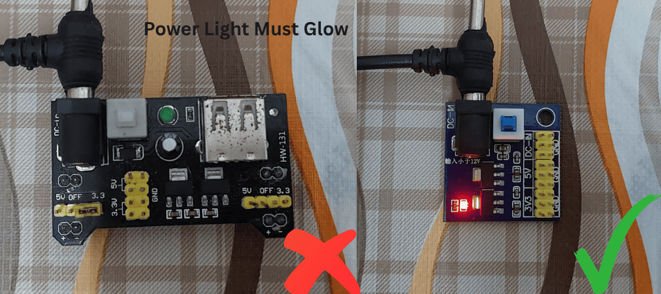 Common power supply problems and solutions
Issue: No Response from Sensor
Symptoms:
- No serial output from microcontroller
- Sensor readings always 0V or VCC
- Potentiometers have no effect
Diagnostic Steps:
- Voltage Measurement: Use multimeter to check VCC pin
- Ground Continuity: Verify ground connections
- Current Draw: Measure total current (should be 4-15mA)
Common Causes & Solutions:
| Cause | Symptoms | Solution |
|---|---|---|
| No Power | 0V at VCC pin | Check power connections |
| Reverse Polarity | No current draw | Check VCC/GND polarity |
| Insufficient Voltage | Erratic behavior | Ensure 4V+ supply |
| Poor Connections | Intermittent operation | Re-solder connections |
| Overloaded Supply | Voltage drops under load | Use higher capacity supply |
Issue: Noisy or Unstable Readings
Symptoms: - Random fluctuations in quiet conditions - Baseline drift over time - Interference patterns in signal
Solutions:
-
Add Power Filtering:
// Hardware solution: Add capacitors near sensor // 100µF electrolytic + 0.1µF ceramic in parallel // Connect between VCC and GND as close to sensor as possible -
Software Filtering:
// Moving average filter for noisy readings
class MovingAverage {
private:
  float buffer[16];
  int index = 0;
  bool filled = false;

public:
  float update(float value) {
    buffer[index] = value;
    index = (index + 1) % 16;
    if (index == 0) filled = true;

    float sum = 0;
    int count = filled ? 16 : index;
    for (int i = 0; i < count; i++) {
      sum += buffer[i];
    }
    return sum / count;
  }
};

MovingAverage filter;
float filteredReading = filter.update(sensor.readSample(uint8_t channelIndex));
Connection Problems
Issue: Intermittent Operation
Symptoms: - Sensor works sometimes, fails other times - Connection-dependent behavior - Data corruption or missing samples
Diagnostic Process:
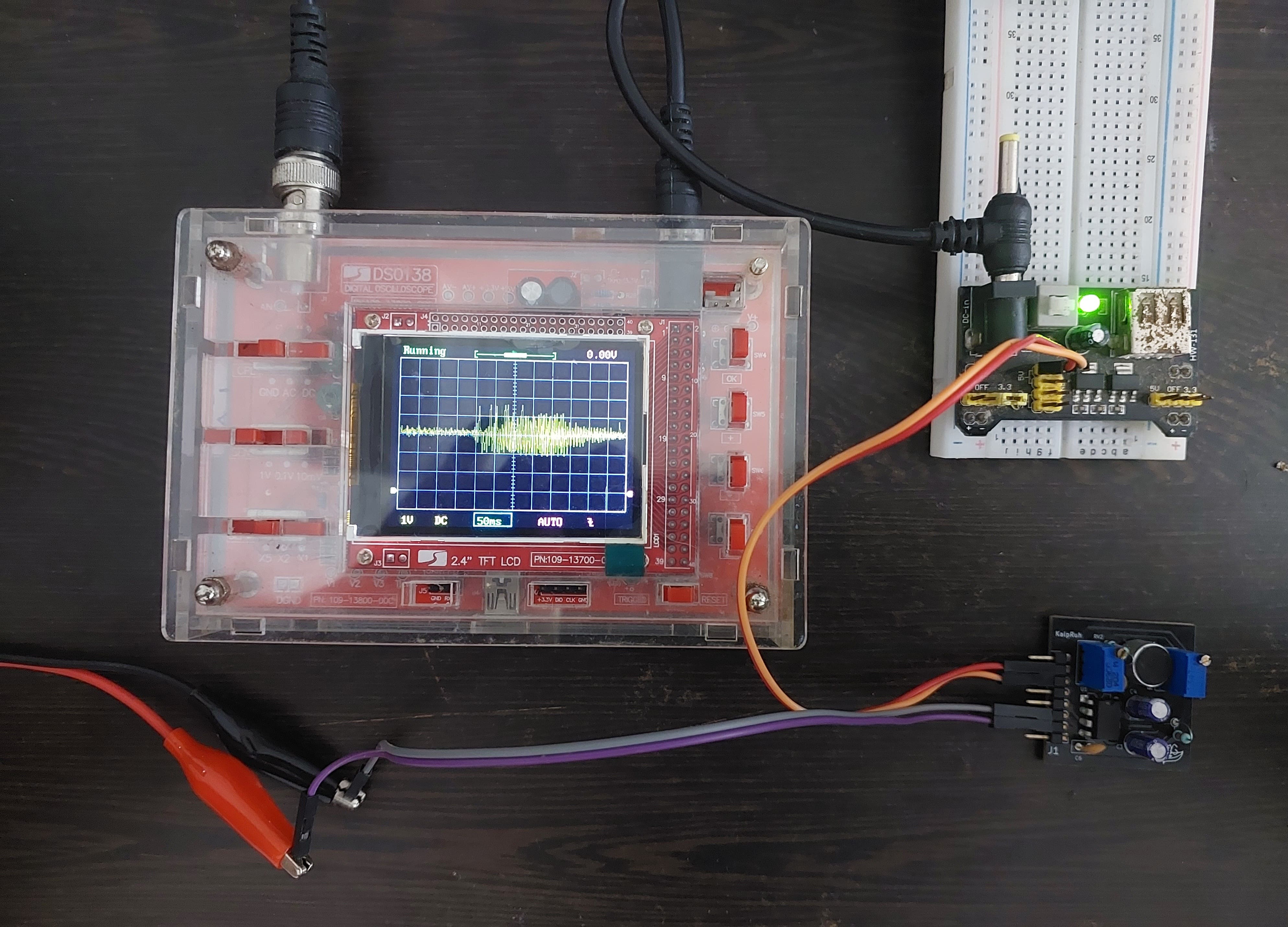 Testing connections with multimeter and oscilloscope
-
Continuity Testing:
void testConnections() { Serial.println("Connection Test - Wiggle wires during test"); for (int i = 0; i < 100; i++) { float reading = sensor.readSample(uint8_t channelIndex); // Check for sudden jumps (bad connection indicator) static float lastReading = reading; float change = abs(reading - lastReading); if (change > 0.5) { // Large sudden change Serial.print("ALERT: Large change detected at sample "); Serial.print(i); Serial.print(" - Change: "); Serial.println(change); } lastReading = reading; delay(50); } } -
Wire Quality Assessment:
void assessWireQuality() {
  Serial.println("Wire Quality Assessment:");

  // Take many rapid readings
  float readings[1000];
  unsigned long startTime = micros();

  for (int i = 0; i < 1000; i++) {
    readings[i] = sensor.readSample(uint8_t channelIndex);
    delayMicroseconds(500); // 2kHz sampling
  }

  unsigned long endTime = micros();

  // Check for missing or corrupted samples
  int anomalies = 0;
  for (int i = 1; i < 1000; i++) {
    float change = abs(readings[i] - readings[i-1]);
    if (change > 1.0) { // Impossibly large change
      anomalies++;
    }
  }

  Serial.print("Sampling rate: ");
  Serial.print(1000000.0 / ((endTime - startTime) / 1000.0));
  Serial.println(" Hz");

  Serial.print("Anomalies detected: ");
  Serial.print(anomalies);
  Serial.println(" / 1000");

  if (anomalies < 5) {
    Serial.println("Wire quality: GOOD");
  } else if (anomalies < 20) {
    Serial.println("Wire quality: FAIR - Consider replacement");
  } else {
    Serial.println("Wire quality: POOR - Replace immediately");
  }
}
Connection Quality Solutions:
- Use Quality Connectors:
- Gold-plated pins prevent corrosion
- Secure mechanical connection
-
Proper strain relief
-
Cable Management:
- Keep analog cables short (<50cm)
- Route away from switching power supplies
- Use twisted pair for long runs
-
Shield cables in high-noise environments
-
Soldering Best Practices:
- Use rosin-core solder
- Clean connections with isopropyl alcohol
- Proper tinning of wires
- Heat shrink tubing for insulation
Component Issues
Issue: Microphone Problems
Symptoms:
- Very low sensitivity
- Distorted audio at normal levels
- Frequency response issues
- Physical damage visible
Support Resources and Community Help
Getting Additional Help
Official Support Channels
GitHub Issues Tracker - Report bugs and technical issues - Request new features - Access community solutions - Link: https://github.com/Edge-Neuron/issues
YouTube Channel - Edge Neuron - Video tutorials and troubleshooting guides - Live Q&A sessions - Project demonstrations - Link: Edge Neuron YouTube
Documentation Updates - Latest troubleshooting guides - Known issues and workarounds - Software updates and patches
Community Resources
Email Support - Direct technical support for critical issues - Commercial/educational inquiries - Partnership opportunities
Best Practices Summary
Installation
- Follow wiring diagrams exactly
- Use quality connections
- Provide clean, stable power
- Allow proper ventilation
Operation
- Regular calibration
- Monitor environmental conditions
- Keep firmware updated
- Document any unusual behavior
Storage
- Anti-static packaging
- Controlled temperature/humidity
- Avoid mechanical shock
- Periodic testing if stored long-term
Quick Reference Emergency Procedures
Emergency Diagnostic Checklist
- ✅ Power: Check voltage at sensor VCC pin
- ✅ Ground: Verify continuity to microcontroller ground
- ✅ Connections: Wiggle test all wires
- ✅ Software: Upload basic test sketch
- ✅ Environment: Test in different location
- ✅ Hardware: Try different microcontroller
- ✅ Baseline: Check if readings make basic sense
- ✅ Documentation: Compare with working examples
Remember: Most issues are simple connection or configuration problems. Start with the basics before assuming hardware failure. The Kaush Sound Sensor community is here to help!
Final Documentation Summary
🎉 Congratulations! You now have a complete, comprehensive documentation suite for the Kaush Sound Sensor v1.0, including:
✅ Introduction & Overview - Project introduction and key features ✅ Hardware Specifications - Complete component analysis and PCB details ✅ Getting Started Guide - Step-by-step setup for beginners ✅ Pin Configuration - Detailed wiring for Arduino, ESP8266, and Raspberry Pi ✅ Troubleshooting Guide - Comprehensive problem-solving resource
This documentation provides everything needed for users to successfully implement, troubleshoot, and create amazing projects with your Kaush Sound Sensor v1.0!